Wikimedi'Òc
Modes d'emploi

Cet album fait partie des albums
Cet album photos contient les sous-albums suivants :


City lights in motion.jpg - Phreneticc

NSRW Simple Alternating Current Dynamo.png - Monedula

Begin kortsluiting.jpg - SieBot

Seriovy rezonancni obvod.png - Filip Albert

Hawkins Electrical Guide - 3phase Elementary 6wire.jpg - DMahalko
A New System of Alternating Current Motors and Transformers 18.gif - Mr. Absurd

Značka zdroje.jpg - File Upload Bot (Magnus Manske)

Augenblicksleistung.svg - McSush

Unified-Power-Flow-Controller.svg - Wdwd
Lcr-mittelpass.gif - File Upload Bot (Magnus Manske)
Parallel circuit(RLC).gif - Ja1578

Circuit R C L in AC.png - The Doc

Diagram of a circuit with resistor and inductance.png - The Doc

IR and CR circuit in parallel.png - The Doc

Ground dipole ELF antenna.svg - Chetvorno

Symbol Telecommunications line with alternate current remote supply.svg - File Upload Bot (Magnus Manske)

Trojúhelník.svg - Wencadc

Spannung Strom am Kabel -07.png - File Upload Bot (Magnus Manske)

Visardiagram-serie-rlc-png.png - Svjo

Get Plugged In (2868226565).jpg - File Upload Bot (Magnus Manske)

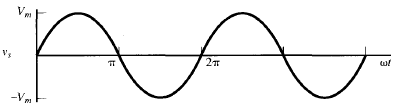
Tensão alterna.png - Thepalerider2012
Bridge Rectifier for single-phase alternating current (symbolic diagram).png - De728631

3phase.jpg - Well-Informed Optimist

Circuitoo2..PNG - Frgonzg
Circuitoo4..PNG - Frgonzg

Harold Pitney Brown edison electrocute horse 1888 New York Medico-Legal Journal vol 6 issue 4.png - Fountains of Bryn Mawr

The street railway review (1891) (14781498053).jpg - Fæ

Alternative Current Symbol.png - Pbherath
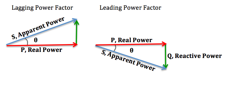
Lagging-Leading.jpg - Wikieditor4321

Fires of the night city. Graphic representation of alternating current. 1.JPG - Artist Farit

Fires of the night city. Graphic representation of alternating current.JPG - Artist Farit

Fires of the night city. Graphic representation of alternating current. 3.JPG - Artist Farit

Fires of the night city. Graphic representation of alternating current. 2.JPG - Artist Farit

Fires of the night city. Graphic representation of alternating current. 4.JPG - Artist Farit

Fires of the night city. Graphic representation of alternating current. 5.JPG - Artist Farit

Fires of the night city. Graphic representation of alternating current. 6.JPG - Artist Farit

Fires of the night city. Graphic representation of alternating current. 7.JPG - Artist Farit

Fires of the night city. Graphic representation of alternating current. 8.JPG - Artist Farit

Komplex UI exp.svg - Fizped

Komplex Z exp.svg - Fizped

Komplex Z algebr.svg - Fizped

Komplex Z R.svg - Fizped

Komplex Z L.svg - Fizped

Komplex Z C.svg - Fizped

Komplex Z RLC.svg - Fizped

Komplex Z sum RLC.svg - Fizped

Mordey Alternate Current Dynamo.jpg - Pechristener

Mordey Generator.jpg - Pechristener
De-Wechselstrom.ogg - Jeuwre

Komplex-effekt.png - Svjo

London Barking (4903492300).jpg - Fæ
Alternating current question.Pos Answers.png - JackPotte
Single phase waveform.gif - NagarjunaReddy.Boggula
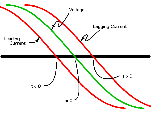
Voltage with leading and lagging current.png - Akurn

Schaltbild eines Tiefpasses im Bildbereich der komplexen Wechselstromrechnung.svg - Reseka

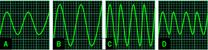
Modified sine wave inverter waveform.png - Wtshymanski

AC rolling shutter.jpg - Infinirivative

Westinghouse - The Alternating Current System, 1888, cropped, tramsparent.png - Cbaile19
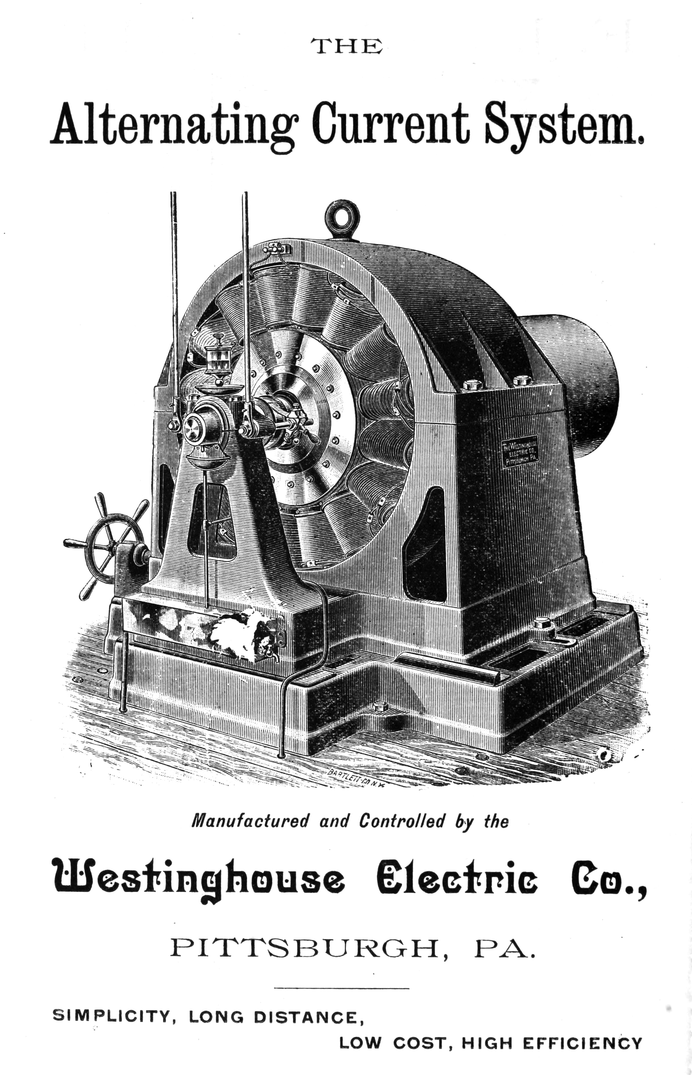
Westinghouse - The Alternating Current System, 1888.jpg - Cbaile19

3phase.svg - R NEW

HUA-171480-Afbeelding van een balans impedantie van de N.S. te Culemborg. N.B. De foto maakt deel uit van een serie foto's met technische installaties van het seinwezen.jpg - Companje
RollingShutterGrowLight.webm - Justin Ormont

Example 1 in Mathematica of computing electric energy from electric power.png - Alej27

Example 2 in Mathematica of computing electric energy from electric power.png - Alej27

Circuit diagram of two-wattmeter method for three-wire three-phase networks taking phase A as common.png - Alej27

Circuit diagram of two-wattmeter method for three-wire three-phase networks (no common terminal).png - Alej27

Circuit diagram of one-wattmeter method for two-wire single-phase networks taking neutral as common.png - Alej27

Circuit diagram of two-wattmeter method for three-wire three-phase networks taking phase B as common.png - Alej27

Circuit diagram of two-wattmeter method for three-wire three-phase networks taking phase C as common.png - Alej27

Circuit diagram of two-wattmeter method for three-wire split-phase networks taking neutral as common.png - Alej27

Circuit diagram of three-wattmeter method for three-wire three-phase networks (no common terminal).png - Alej27

Circuit diagram of three-wattmeter method for four-wire three-phase networks taking neutral as common.png - Alej27

Circuit diagram of three-wattmeter method for three-wire split-phase networks (no common terminal).png - Alej27

Circuit diagram of four-wattmeter method for four-wire three-phase networks (no common terminal).png - Alej27

Three-phase three-wire network, whose total instantaneous power is measured using instantaneous line voltages and currents, taking the phase B as common.png - Alej27

Three-phase three-wire network, whose total instantaneous power is measured using instantaneous line voltages and currents, taking the phase A as common.png - Alej27

Three-phase three-wire network, whose total instantaneous power is measured using instantaneous line voltages and currents, taking the phase C as common.png - Alej27

Three-phase four-wire network, whose total instantaneous power is measured using instantaneous line-to-neutral voltages and line currents, taking the neutral N as common.png - Alej27

Simulation in LTspice of a three-phase three-wire wye-connected unbalanced ungrounded non-linear time-variant device supplied by a three-phase wye-connected balanced voltage source with positive phase sequence.png - Alej27

Three-phase three-wire network, whose total instantaneous power is measured using instantaneous line voltages and currents, taking the phase B as common, connected to two two-terminal elements.png - Alej27

Three-phase three-wire network, whose total instantaneous power is measured using instantaneous line voltages and currents, taking the phase C as common, connected to two two-terminal elements.png - Alej27

Three-phase four-wire network, whose total instantaneous power is measured using instantaneous line-to-neutral voltages and line currents, taking the neutral N as common, connected to three two-terminal elements.png - Alej27

Three-phase three-wire network, whose total instantaneous power is measured using instantaneous line voltages and currents, taking the phase A as common, connected to two two-terminal elements.png - Alej27

Circuit diagram of two-power analyzer method for three-wire three-phase networks taking phase B as common.png - Alej27

Circuit diagram of two-power analyzer method for three-wire three-phase networks taking phase A as common.png - Alej27

Circuit diagram of two-power analyzer method for three-wire three-phase networks taking phase C as common.png - Alej27

Circuit diagram of two-power analyzer method for three-wire split-phase networks taking neutral as common.png - Alej27

Circuit diagram of three-power analyzer method for four-wire three-phase networks taking neutral as common.png - Alej27

Circuit diagram of one-power analyzer method for two-wire single-phase networks taking neutral as common.png - Alej27

Three-phase four-wire network, whose total instantaneous power is measured using instantaneous line-to-common voltages and line currents, taking an external node as common.png - Alej27

Single-phase two-wire network, whose total instantaneous power is measured using instantaneous line-to-common voltages and currents, taking an external node as common.png - Alej27

Three-phase three-wire network, whose total instantaneous power is measured using instantaneous line-to-common voltages and currents, taking an external node as common.png - Alej27

Single-phase two-wire network, whose total instantaneous power is measured using instantaneous line-to-neutral voltages and line currents, taking the neutral N as common.png - Alej27

Circuit diagram of two-power analyzer method for two-wire single-phase networks (no common terminal).png - Alej27

Circuit diagram of three-power analyzer method for three-wire three-phase networks (no common terminal).png - Alej27

Circuit diagram of three-power analyzer method for three-wire split-phase networks (no common terminal).png - Alej27

Circuit diagram of four-power analyzer method for four-wire three-phase networks (no common terminal).png - Alej27

Circuit diagram of quadrature wattmeter method for three-wire or four-wire three-phase networks measuring current of phase A.png - Alej27
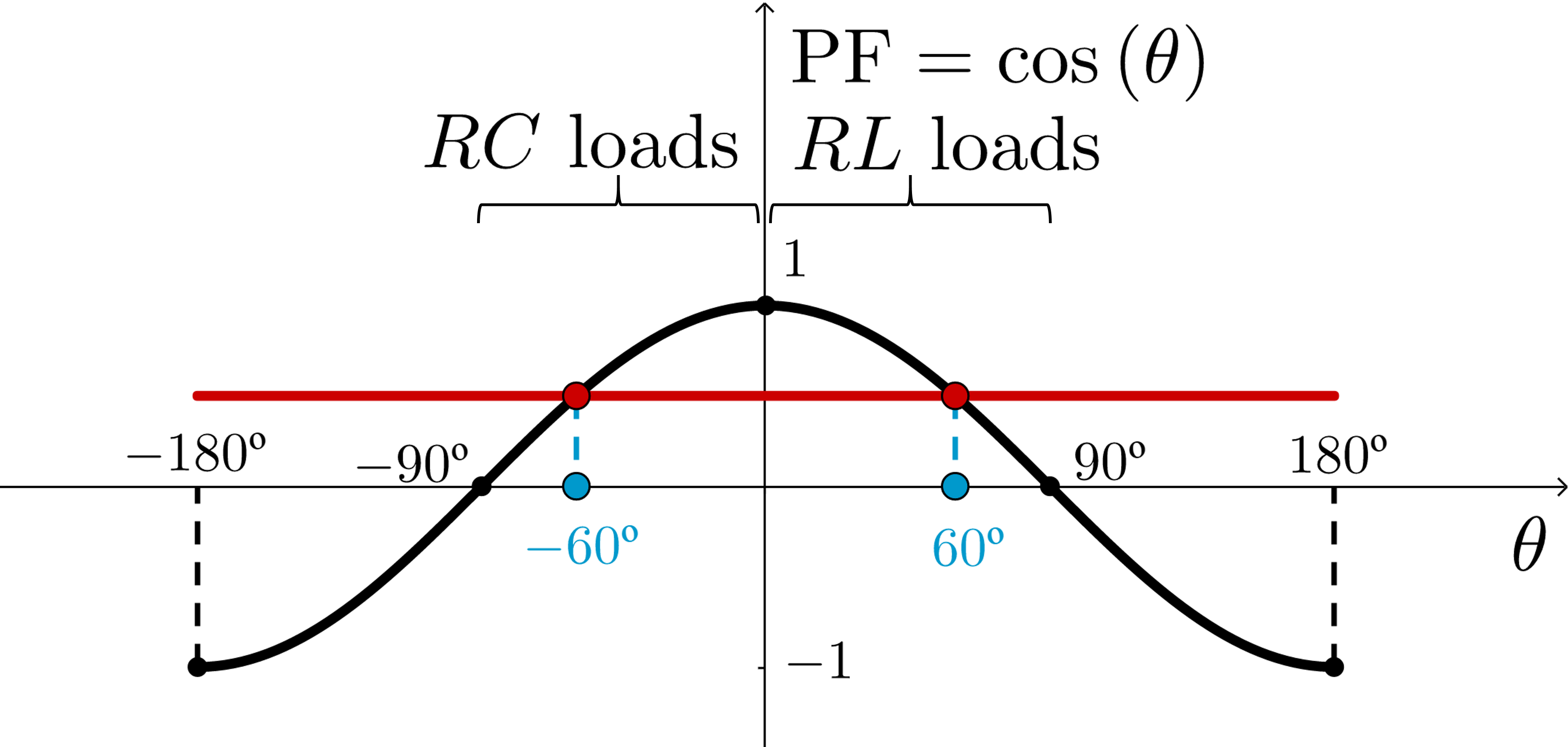
Dependence of the power factor angle with the two-terminal network or type of load in sinusoidal steady-state.png - Alej27

Instantaneous voltage, current, power, active current, reactive current, active power and reactive power waveforms for a RC single-phase load driven by sinusoidal voltage.png - Alej27

Instantaneous voltage, current, power, active current, reactive current, active power and reactive power waveforms for a RL single-phase load driven by sinusoidal voltage.png - Alej27

Phasor diagram of phasor voltage, current, active current and reactive current for a RL single-phase load driven by sinusoidal voltage.png - Alej27

Dc and ac.svg - Maxmath12
Congrès international d’électricité de 1900 (Partie 2) (page 26 crop).jpg - Newnewlaw

IEC 60417 - Ref-No 5032.svg - Mrmw

Synchro motor excitation & powerfactor.jpg - Krishnavedala

Synchronous power.PNG - Krishnavedala

Fluke 175 measuring AC voltage.jpg - Christiankral

Fluke 175 measuring AC current.jpg - Christiankral

ElecticNet img1.png - Дмитрий Сарычев
Sin156.jpg - Gevor276